Inconsistent parts are one of those problems that can drive a production team nuts.
You tweak the machine. You slow the feed. You adjust the pressure. You try a different operator. And somehow you’re still chasing the same issues: wrinkling, marking, hole drift, burrs, scratches and parts that “almost” look right.
A lot of people assume those problems are always caused by the machine.
Most of the time, they’re not.
In our world, inconsistency usually starts with tooling and material behavior. If you don’t control what the material wants to do under pressure, it’s going to do it anyway… and you’ll see that show up in your parts.
This is a breakdown of the real tooling issues we see most often, and how we design around them at Minland Machine.
The Most Common Tooling Problem for Benders
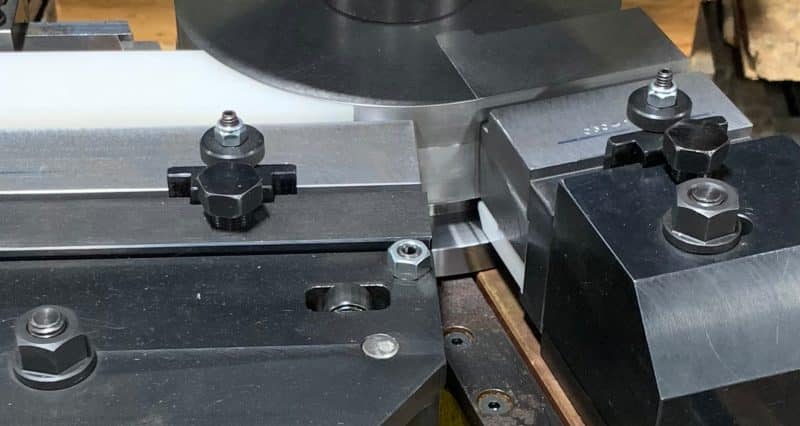
If you’ve ever bent an extruded aluminum profile, you’ve probably seen this one.
A lot of profiles have an inside leg on the inside radius, usually a feature that holds trim, a seal or something cosmetic. That inside leg is also the part that loves to wrinkle first.
Why?
Because when the material compresses during the bend, it has to go somewhere.
If you imagine that inside leg getting pushed and trapped while the bend happens, the aluminum is going to try to move, buckle or wrinkle in whatever direction it can. That’s why we focus so hard on controlling the inside radius and that inside leg.
On bends like this, the critical point is controlling the thickness gap right where the part wants to wrinkle.
Powder Coat Can Destroy Your Tolerance (Even When the Extrusion Is Fine)
Here’s a big one that people don’t expect until they’re living through it:
Sometimes the extrusion is consistent … but the powder coat isn’t.
When we’re running tight tolerance work, you might be trying to hold something like plus or minus 0.0005″. In some cases you can get away with 0.001″, depending on the application.
But then the customer brings you powder coated material and the coating thickness can vary so much that it wipes out the tolerance by itself.
We’ve seen situations where the powder coat build is around 0.004″ tapered over a small critical area.
That doesn’t sound like much until your tooling is designed around a very specific controlled gap.
Now instead of predictable bending, you’re chasing part-to-part inconsistencies because the coating thickness is doing whatever it wants.
The practical fix: shim it and move on
Powder coat thickness variation is often just the nature of the beast. It depends on how it’s sprayed, the part geometry and the process.
So what do we do?
We build in the ability to adjust it. A lot of times that means providing shims so the customer can add or subtract thickness in the tooling to dial it in.
Not glamorous, but it works.
A Tooling Upgrade That Immediately Improved Consistency
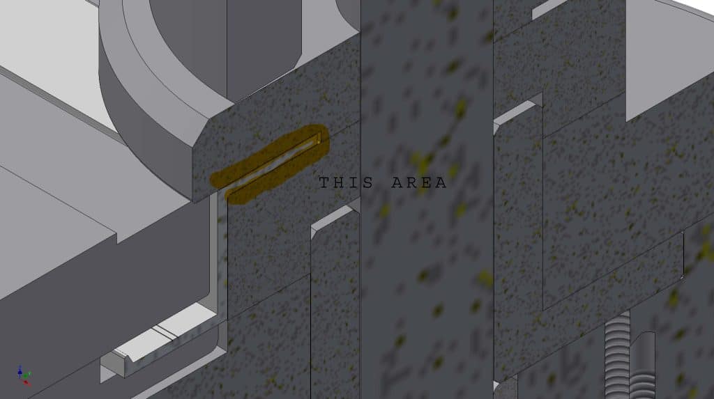
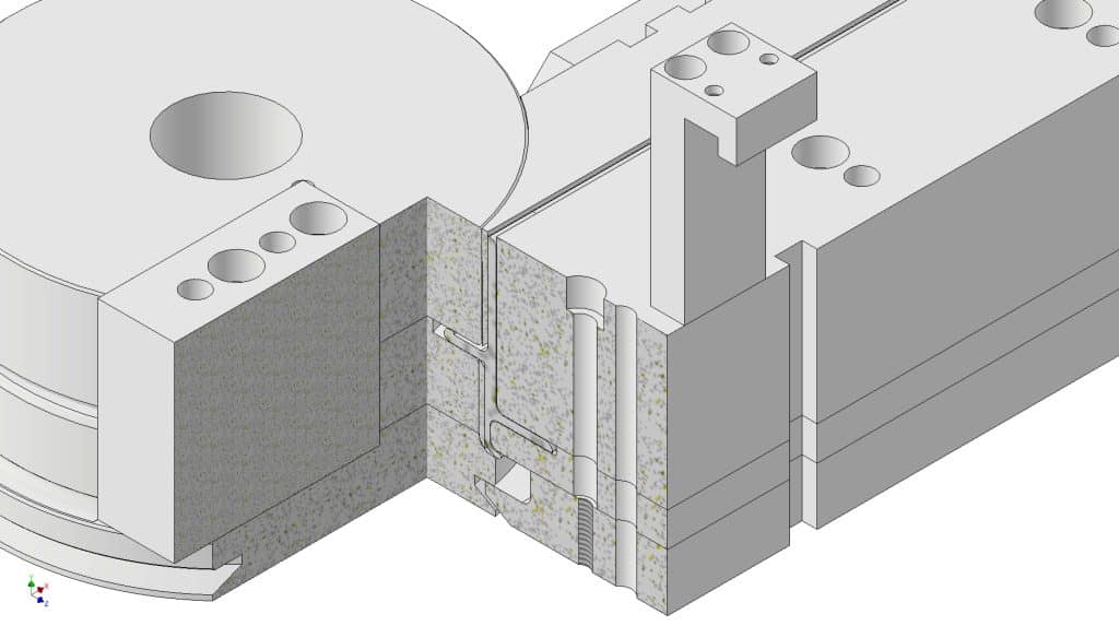
One of the simplest improvements we’ve made in bending tooling is adding a wiper.
A lot of people don’t use a wiper at all, and then they’re surprised when the inside leg starts bunching up and wrinkling before it ever gets into the die.
The wiper is a piece of tooling that runs on the inside and controls what the material is allowed to do before it hits the main forming area.
The wiper controls the “pre-wrinkle” zone
Think of it like this:
When you’re bending a profile, you’ve got a single point in the forming area that traps the material and forces it into shape. But before it hits that point, the material can start to bunch up.
That’s where instability starts.
A wiper acts like a lead-in control. It helps prevent the material from ballooning out or stacking up before it enters the forming zone.
Auto Punching: Most of the Problems Aren’t the Punch
We get asked a lot about punch issues such as misfeeds, hole position drift, burrs and ugly holes.
The truth is our auto punch setups are typically pretty flawless.
When something does go wrong, it’s usually tied to the feed system or material behavior, not the punch itself.
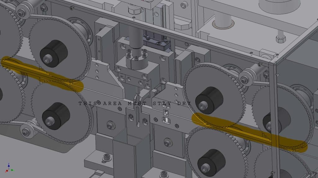
Belt wear causes hole-to-hole tolerance drift
If your hole-to-hole tolerance starts wandering, you’re usually seeing wear in the belts.
And the belts wear down faster when customers do things they think are “helpful.”
The most common mistake: adding lubrication
Our punch machines are built to run dry. The rubber belts do not like lubrication. But customers will sometimes try to lubricate anyway, thinking:
“If we’re punching aluminum, lubrication has to help.”
What they don’t realize is lubrication can soften or damage the belts, cause feed drift and create accuracy problems that show up as hole position inconsistencies.
So if you’re struggling with accuracy and you’re adding lubrication, that’s a red flag.
How Raw Aluminum Sticks to the Auto Punch
If you run raw, uncoated, soft aluminum, there’s a chance it starts sticking to the punch.
When that happens, the punch gets buildup, and now you’ve got a chain reaction: the holes start looking bad, the part gets scratched, that transfers to the next part, and now everything looks like junk.
That’s where people start saying:
“Something’s wrong with the punch.”
Usually it’s not the punch.
It’s what the aluminum is doing under that surface condition.
One workaround: alternate with harder, finished material
If you can alternate runs between raw and painted/hardened material, the harder surface helps keep the punch cleaner.
If all you run is raw aluminum all day long, you’re more likely to fight sticking.
Sometimes there isn’t a perfect solution, just the best workaround for the material you’re dealing with.
The Linear Grind Punch: Small Detail, Huge Difference
This is one of those things that sounds minor until you see the impact.
A typical round punch is ground around the diameter. That can create microscopic highs and lows on the surface. Those highs and lows grab raw aluminum. Then material starts building up on the punch. And then your holes look bad and your parts get scratched.
A linear grind punch is ground lengthwise instead.
So instead of circular grind marks that can grab material, the grooves run up and down, giving aluminum less opportunity to catch and stick.
Mechanical vs. Rubber Strippers
We can use a mechanical stripper or a rubber stripper.
Mechanical stripper (standard and preferred)
This is the best setup because it’s integrated into the control. It moves up and down, traps the material, holds it down during punching and keeps everything stable. It’s reliable, and you don’t constantly mess with it.
Rubber stripper (only when it’s actually needed)
Sometimes we’ll add a rubber stripper to help keep a punch cleaner when material is sticking.
But rubber strippers are wear items.
They can have a short lifespan (sometimes daily changes, sometimes every couple days), and they’re not cheap. So we don’t recommend making rubber the default. We use it when the job demands it.
Wear & ‘Tooling Drift’ Over Time
Another big issue people underestimate is tooling wear. You can make tooling out of cheaper material like 1018 steel and it’ll work… for a while.
Then it starts wearing.
And once it wears, you get wrinkling returning, a loss of consistency and are fighting tolerances constantly.
That’s why our tooling is made with heat-treated tool steel. Wear becomes predictable instead of chaotic, and you’re not chasing the tooling as it changes shape over time.
A Tough Tooling Truth
Tooling is only as accurate as the data you give us.
Many customers don’t have proper files for their extrusion. Or they send samples that aren’t final. Or they’re trying to build tooling for a profile that doesn’t even exist yet.
Then we’re stuck reverse engineering something that may not match the final extrusion anyway.
That’s when you get the painful part. We grind here, adjust there through trial and tweaking. That’s not the ideal way to do it, but it happens.
For the process to go smoothly, we prefer customers send us .STP files. DXF files can work too (we can convert them to solid models).
Auto Punch Constraints That Catch People Off Guard
When crafting an Auto Punch for specific applications, it helps for our team to know things like:
- What’s the narrowest area we can drive with the belts?
- Do the belts need to sit inside a groove?
- How close to the edge does that hole need to be?
- What hole sizes are required (and what does that mean for changeover)?
- How consistent is the material thickness?
Most punch/die clearance is based on roughly 8–10% of material thickness.
If your thickness varies too much, you can get burrs, ugly holes, too much punching force and inconsistent results.
If you’re not within something like 0.020–0.030″ thickness consistency, you’re risking problems. The key is accuracy, and a solid STP file goes far.
Material Handling Is Part of the System
Here’s something people don’t always consider when seeking an Auto Punch:
Infeed and outfeed on our punch machines require the customer to build tables or supports in their environment. We’ll offer a heads-up and can consult with with customers on possible configurations, but the responsibility ultimately falls on the machine’s recipient.
Want Us to Review Your Part & Point Out the Risk Areas?
If you’re fighting wrinkling, ugly holes, scratches or “we swear it was fine yesterday” inconsistency, send us your profile and tell us what you’re trying to run.
We’ll take a look and tell you what’s going to cause trouble, what to fix first and what kind of tooling approach makes sense before you burn time and material chasing the wrong solution.