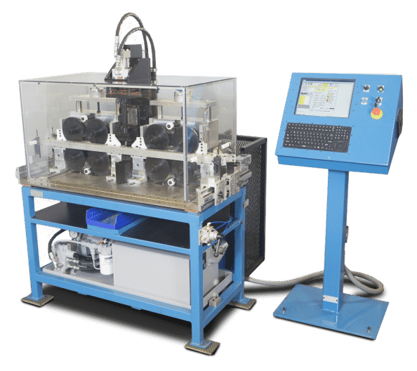
Safety First: Verify guards are in place and the area is clear before powering the machine.
1.) Turn Main Power ON at the back of the electrical enclosure.
2.) Turn Power Switch ON at the computer console.
The PC auto-starts; the green Power On light should be lit.
The AutoPunch software launches automatically.
3.) Log in with your credentials.
4.) Release (pull) the red E-Stop.
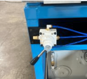
5.) Press Pump On.
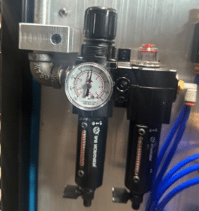
6.) Confirm plant air: 80 psi to the filter air regulator.
7.) The last program used will load automatically.
8.) Turn Clamp-1 Down to the lowered position.
9.) Press RUN to download the program to the PLC.
10.) Verify motion: the feeder position counts and bottom rollers spin.
2. Machine Shut Down
Important: Do not turn off main power until the PC has fully shut down.
1.) Press Stop to halt the machine.
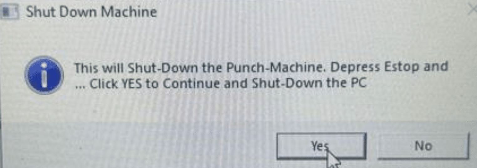
2.) Press the red E-Stop to disable machine functions.
3.) Press Log Off in the software and confirm Yes to initiate shutdown.
Allow the computer to shut down completely.
4.) Switch the console power OFF.
5.) Turn Main Power OFF at the electrical enclosure.
3. Setup Procedure
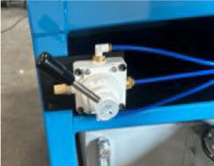
1.) Ensure the hydraulic pump is ON.
2.) In the AutoPunch software, press Stop.
3.) Raise Clamp-1 to the up position.
4.) Loosen the ¼-20 wing nuts on the material roller guide rails (¼–½ turn).
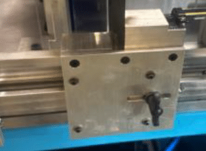
5.) Set the rear guide rail to the target position and tighten the lock bolts.
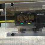
Use precision calipers to verify rail height left/right.
6.) Use a Mitutoyo scale to position hole locations front-to-back.
7.) Insert material so it extends from both ends of the machine.
8.) Hold material against the back rollers and lower Clamp-1.
9.) Slide the front guide rail back until it lightly touches material at both ends.
Re-adjust to leave a 0.005–0.010 in gap; tighten lock bolts.
10.) Raise Clamp-1.
11.) Remove the material from the machine.
12.) Lower Clamp-1 again.
13.) The machine is ready to run.
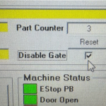
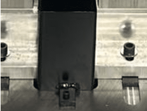
4. Gate (Part Separation Sensor)
Each extrusion must enter the guide rollers with a small gap between pieces so the edge fiber-optic sensor can reset and start the next cycle.
Enabling the Gate helps prevent misfeeds: it lowers until the sensor detects the extrusion has passed, then lifts to admit the next piece.
After operators are comfortable, you may disable the Gate to maximize throughput.
5. Speed Control
Set machine speed using the Speed slider; speed is a percentage of maximum.
The speed setting is saved with the program and restored the next time it runs.
Note: Hole spacing on most extrusions limits top speed; maximum may not be reached in typical parts.
6. Passwords
To change the password:
Select Setup → Machine Parameters.
Open the Password tab.
Enter the current password.
Enter the new password, then re-enter to verify.
Click Apply.
7. Air Pressure Settings
Point
Pressure
Main Air Supply
80 psi
Clamp-1 Down Regulator
8 psi
Clamp-2 Down Regulator
8 psi
8. Lubrication
There is one grease fitting on the punching head slide.
Lubricate once per month, approx. 1 cc.
Use general-purpose lithium-based grease.
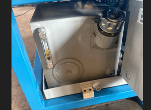
Verify hydraulic fluid level; add AW-46 as needed.
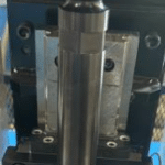
9. Adjusting Punch Depth
1.) Switch Guard OFF at the computer console.
2.) Open the guard door.
3.) Turn the hydraulic pump ON.
4.) Press Punch Down on the console.
5.) Loosen the 5/16-24 SHCS (¼ turn).
6.) Rotate the Ram Rod to the desired height.
7.) Tighten the clamp.
8.) Press Punch Up.
9.) Close the guard door.
10.) Switch Guard ON at the console.
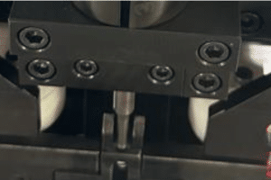
10. Replacing the Top Punch
Caution: Keep fasteners and mating surfaces clean. Do not over-tighten small screws.
Removal & Replacement
1.) E-Stop the machine.
2.) Open the guard door.
3.) Remove ¼-20 bolts from the punch block.
4.) Remove the (4) #4-40 flat-heads from the hardened backer.
5.) Replace the punch.
6.) Reinstall the #4-40 flat-heads; snug only—do not over-tighten.
7.) Clean the punch holder and receiver before reassembly.
8.) Insert the punch block and tighten ¼-20 bolts, maintaining upward pressure during installation.
9.) Close the guard door.
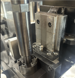
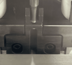
11. Replacing the Lower Die Section
Note on sharpening: If material is removed from the Lower Die Section during sharpening, install a shim of equal thickness under the LDS to maintain tool height.
1.) E-Stop the machine.
2.) Open the guard door.
3.) Remove wing nuts from the front guide rail and remove the rail.
4.) Remove the slug guard from the table.
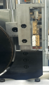
5.) Remove (2) ¼-20 SHCS.
6.) Remove the Lower Die Steel (LDS).
7.) Clean mating surfaces; install the replacement LDS (free of debris).
8.) Install ¼-20 bolts.
9.) Reinstall the slug guard.
10.) Reinstall the front guide rail.
11.) Close the guard door.
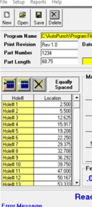
New Program (Create)
1.) From the main screen, select File → New, or click NEW.
2.) In the New Program window:
Name the program and Save.
Enter Part Number (optional).
Enter Print Revision (optional).
Enter Part Length (required).
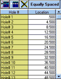
3.) Enter Hole Locations:
Manually type positions or use Equally Spaced to auto-calculate.
4.) Set Machine Speed.
5.) Press RUN.
6.) The Help Bar can open the Frame Designer to assist with hole layout.
13. Entering Hole Locations
For patterns with equal spacing, click Equally Spaced, then enter: Part Length, Distance to First Hole, Distance Between Holes, OK.
To type locations, enter values in sequence; press Enter or arrow keys to advance.
Editing Hole Lists
Delete a hole: Place the cursor on its row and click Delete Row.
Insert a hole: Place the cursor where needed and click Insert Row.
Clear all: Click Clear All.
14. Open Program
1.) Select File → Open or click OPEN on the toolbar.
2.) Choose the program file from the list.
3.) Click Open to load it.
15. Save Programs
Save As (copy or overwrite)
1.) Select File → Save As.
2.) Enter a new file name or select an existing name to overwrite.
3.) Click Save As.
16. Delete Programs
Recovery Note: Deleted programs can be restored only from USB backups. If no backup exists, the file cannot be recovered.
1.) Select File → Delete or click Delete on the toolbar.
2.) Select the file name to delete.
3.) Click Delete.
4.) Confirm YES to permanently remove the file.
17. Backing Up Program Files
Best Practice: Back up programs regularly to protect against system faults or accidental deletion.
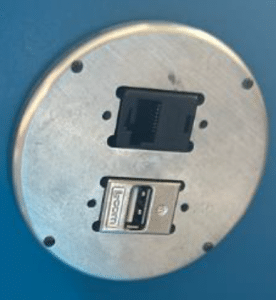
Use the USB port on the bottom of the computer console.
In the software, select File → Save As and save a copy of each program to the USB drive.
Need CNC Expertise?
Minland Machine utilizes the best equipment, technology, and people to produce the highest quality CNC machining in the industry. Contact us for your next project.