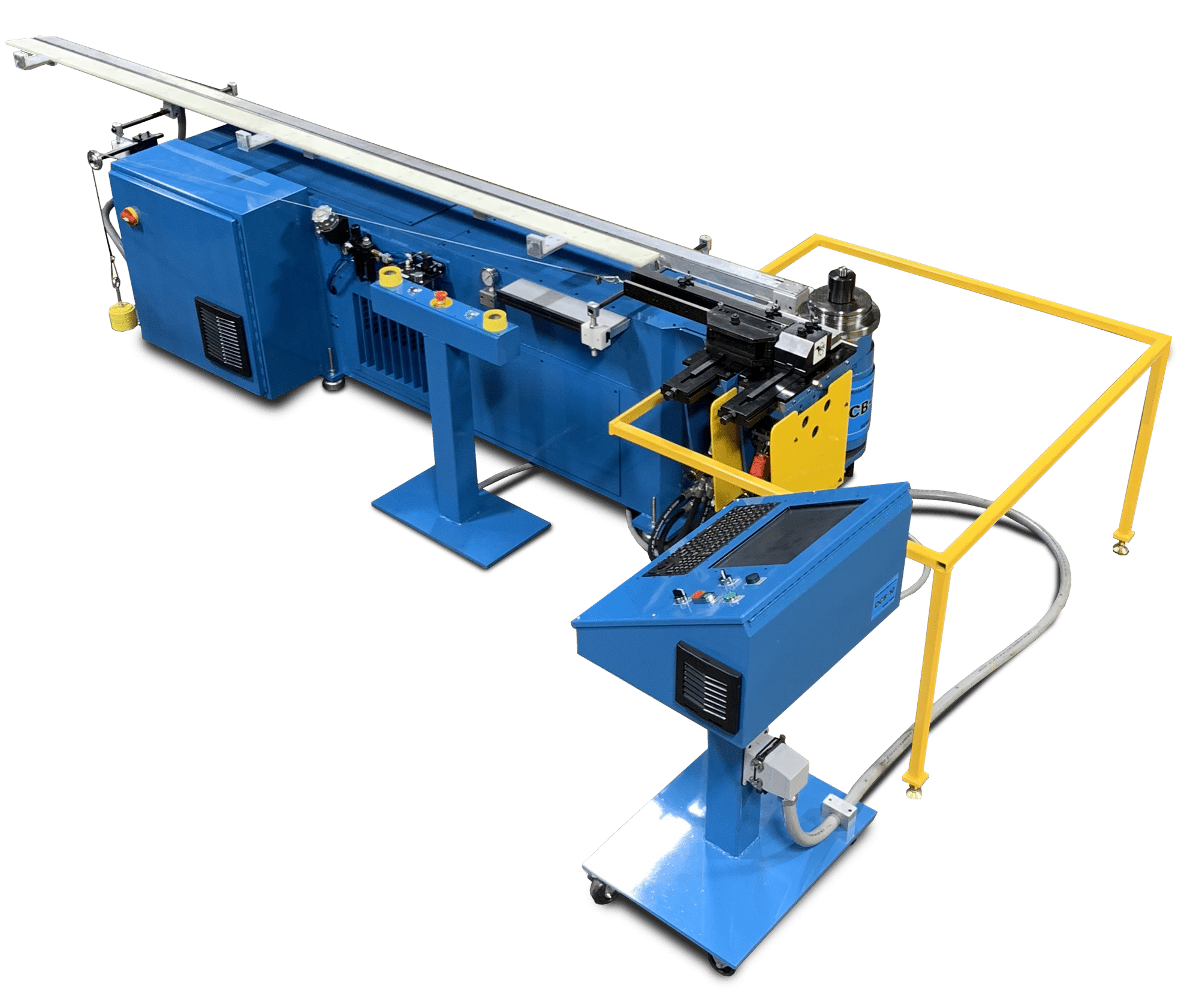
DCB10 Bender Help
Use this page as the online reference for operating, programming, maintaining and troubleshooting the DCB10 series bender.
Quick Index
- Login & User Roles
- Start-Up & Shutdown
- Homing/Referencing
- Programs (Create • Edit • Run)
- Main Screen Overview
- File/Setup/Tools/Help Menus
- Console & Pendant Controls
- Parameters (Stop Table • Swing Arm • Machine Options • Shutdown)
- Datasheet & Machine Setup
- Sub-Systems (Lube • Pneumatics • Hydraulics)
- Safety Plate
- Diagnostics (I/O)
- Alarms
- Troubleshooting
- Machine Fluids
- Support & Registration
1. Login & User Roles
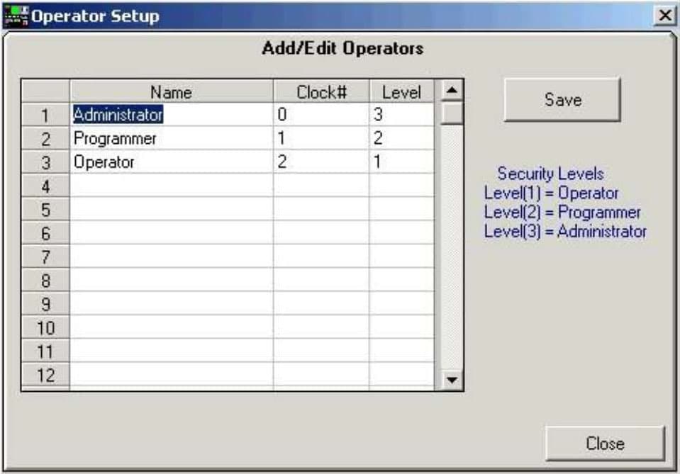
Accounts & Security
The system requires at least one Administrator.
Multiple Administrators, Programmers, and Operators may be defined.
Login uses “Clock #” (case-sensitive; alphanumeric).
Change a user’s security level without recreating their account. (User must log out/in for changes to apply.)
Keep Admin/Programmer codes private to prevent unauthorized parameter/program changes.
Access Levels
Level 1 – Operator: Run programs only.
Level 2 – Programmer: Create/edit/delete programs (no parameter access).
Level 3 – Administrator: Full access, including parameters.
Operator Login
Operators must log in at software start. Access to functions is determined by the user’s Security Level.
Software / Machine Exit Options
- Exit to Windows: Admin only (either already logged in as Admin or supply Admin code at prompt). Use for PC/OS servicing only.
- Shut Down Bender: Normal end-of-day shutdown. Turns the PC off and disables all machine functions; pump turns off automatically.
2. Start-Up & Shutdown
Bender Start-Up (Daily)
Turn main disconnect ON (electrical enclosure).
Green power lamp on console indicates main power.Press PC ON on the console; control software auto-launches after Windows loads.
Release Emergency Stop on the pendant; press Pump ON on the console.
Log in to the software; switch console to Manual.
Reference (Home) the Bend-Arm and the Stop Table.
Install tooling and set clamps/alignments as needed.
Switch to Auto or Semi on the console.
Open the desired part program.
Follow on-screen prompts to begin bending.
Bender Shutdown (Daily)
Two safe methods. Both will stop the pump and power down the PC:
File → Shut Down Bender: Turns off pump and electronics, then powers down the PC.
After PC is fully off, turn off the main disconnect.Press Emergency Stop: A Shut Down Bender screen appears. Click Shut Down Bender.
After PC is fully off, turn off the main disconnect.
Important: Never switch off the main disconnect before the PC has shut down; this can damage the PC.
3. Homing/Referencing
All axes must be homed before running programs. Switch the console to Manual to home.
Swing Arm
- Jog the swing arm forward ~15°.
- Click Reference Swing Arm.
The arm moves to the limit switch, then to the home offset and final stop. Readout shows 0.0° and the button grays out when complete.
Stop Table (Single-Stop)
Jog the stop table forward ~10 in beyond the home switch.
Click Reference Stop Table.
Button turns blue while active; gray when complete.
Stop Table (Multi-Stop)
- Jog the stop table forward ~10 in beyond the home switch.
- Click Reference Stop Table, then YES to home all stops (1…12) to the rear of the rail.
Button turns blue while homing; gray when complete.
4. Programs
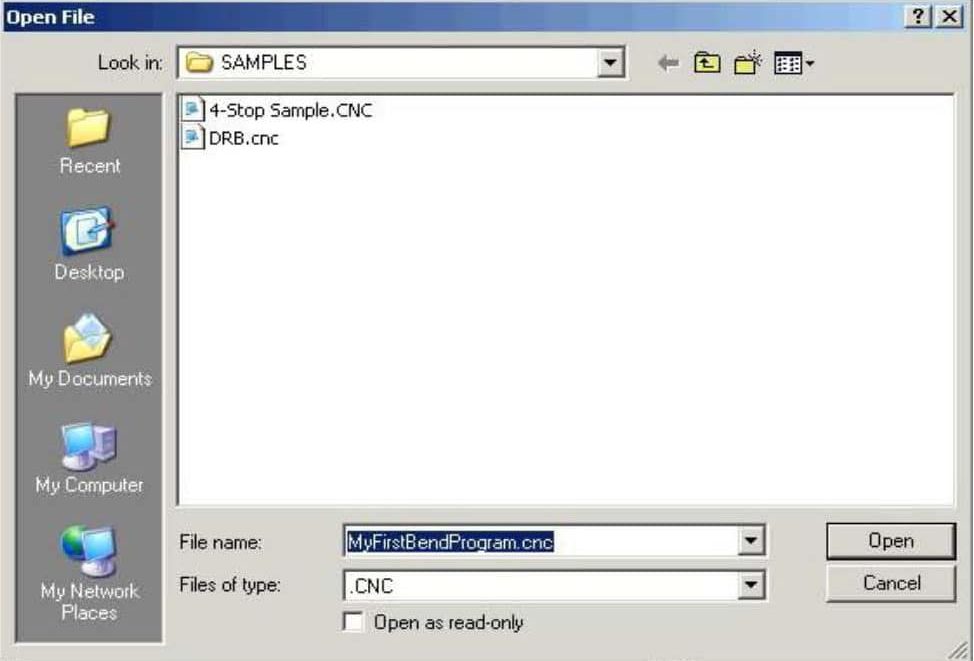
Create a New Part Program
File → New.
Navigate to target folder.
Name the program, e.g.,
MyFirstBendProgram.cnc.Click Open to create a blank file.
All program files must use the .CNC extension.
Program Structure & Rules
- Programs consist of Stops (stop table positions) and Bends (angles + speeds).
- Bend Speeds: 1–100% of max speed.
- Stop 1 is always Absolute.
- Absolute Mode (Abs): All stops measured from spindle center.
- Incremental Mode (Inc): Stop 1 is absolute; subsequent stops measured from the previous stop.
- Bend Angles: 1° to the Max Bend Angle parameter (default 183°).
Global Adjustments (non-destructive)
Adjust all bends or all stops without changing the program:
Global Bend Adjustment: Apply over-bend to compensate for material springback.
Global Stop Adjustment: Apply cut-length corrections across all stops.
Automation Options
Auto Return to Stop 1 (Single-Stop tables only): After the last bend, returns to Stop 1.
Safe Retract Position: On the last bend, retract the stop table to an absolute “safe” distance from spindle center before bending to clear tooling.
Sequence: Operator presses Bend → clamps close → Stop Table retracts & moves to safe position → bend completes → arm returns home → (optional) auto-return to Stop 1.
Edit an Existing Program
File → Open and edit settings. Save to keep changes.
Run a Program
Reference arm & table in Manual (skip if already homed).
Switch to Auto or Semi.
(Optional) Enable Auto Return to Stop 1 and/or Safe Retract Position.
Open the program file.
Single-Stop table: If “Auto Return to Stop 1” is checked, the stop automatically moves to position 1.
Multi-Stop table: System prompts to place all stops to programmed positions.
Press & hold both Bend buttons to start the cycle; you may release after cycle starts (unless “Require hold” is enabled—see Machine Options).
Modes
Auto: Clamp → Bend → Unclamp → Auto return to home.
Semi: Clamp → Bend → Unclamp → Press both Bend buttons again to return arm to home.
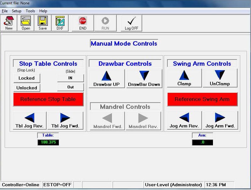
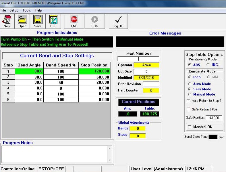
5. Main Screen Overview
- File Path & Current File: Shown at top.
- Status Bar: Controller status, E-Stop state, current user/rights, time.
- New / Open / Save: Program file operations. Save also saves Program Notes and Global Adjustments.
- DXF Viewer: Display an associated part DXF in an embedded viewer (if available).
- Run / End: Start or end a running program.
- Log Off: Sign out and return to login.
- Program Notes: Freeform notes saved with the program.
- Part Number: Optional (can be required via Machine Options).
- Cut Size: Manual reference value for operators.
- Modified: Auto-updated last modified date/time.
- Print Revision: Manual history field for print rev tracking.
- Part Counter: Editable/presettable count of completed parts.
- Current Positions: Live Bend-Arm and Stop-Table readouts.
- Global Adjustments: Non-destructive bend/stop tweaks.
Positioning Modes
- Absolute: Stops measured from spindle center.
- Incremental: Stop 1 absolute; others incremental from the last.
Coordinate Units
Inches + Degrees or Millimeters + Degrees.
Operating Mode Selector (software)
Auto / Semi / Manual (see “Run a Program”).
Mandrel On
Enables mandrel functions if equipped (and option enabled in Machine Options).
Bend Cycle Time
Shows total clamp-bend-unclamp-return time for a completed cycle.
6. Menus
File
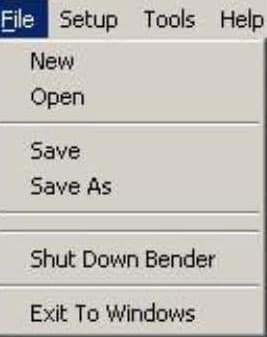
New / Open / Save / Save As
Shut Down Bender: Standard power-down sequence.
Exit to Windows: Admin-only.
Setup
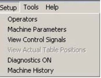
- Operators: Create/edit user accounts (Admin only).
- Machine Parameters: Access/edit parameters (Admin only).
- Diagnostics ON: Technician diagnostic screen.
- View Control Signals: Quick end-user diagnostics for limit switches and pushbuttons.
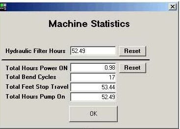
- Machine History: Usage statistics/history.
Tools
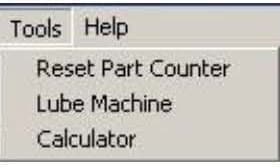
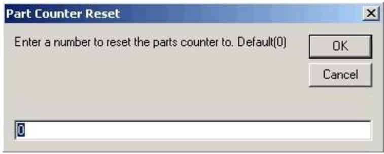
Reset Parts Counter: Preset part count (not limited to zero).
- Lube Machine: Manual lubrication pulse for arm/clamps/slides.
- Calculator: Launches system calculator.
Help
- Contents: Opens this help.
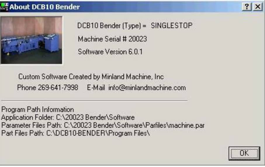
- About: Software/identity info.
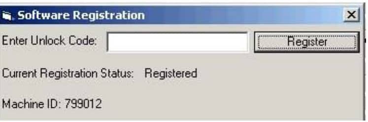
- Registration: Displays license/machine ID. Registration is tied to the motherboard serial number—contact Minland with the Machine ID to obtain a new code.
- Event Log: User action log for troubleshooting.
7. Console & Pendant Controls
Console
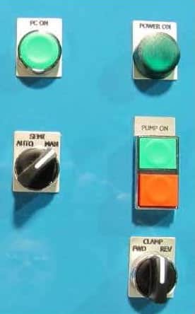
PC ON: Powers the PC.
Power Lamp: Indicates main power at disconnect is ON.
Auto / Semi / Manual: Operational mode selector.
Pump ON / OFF: Start/stop hydraulic pump. Pump also stops by pressing Emergency Stop or pressing the yellow Swing-Arm Safety Plate.
Clamp FWD/REV: Jog clamp and drawbar for setup (holds position when released).
On-screen clamp buttons jog only while pressed.
Pendant

- Bend Buttons A & B (outer buttons): Start a bend cycle.
If “Require hold” is enabled in Machine Options, keep both buttons held for the entire cycle or the arm stops with a FEED HOLD; press again to resume. - Emergency Stop (center): Stops pump, halts motion, terminates any running program.
All axes must be re-referenced after E-Stop. - Advance (single-stop tables only): Manually advance to the next stop when in cycle.
Machine Shutdown
Important: Exit to Windows is available only when logged in as an Administrator.
Warning: Do not turn off the main disconnect until the PC has fully shut down—doing so can damage the computer.
Shut the bender down using one of the two methods below. Both methods automatically turn off the pump, disable electronics, and then shut down the PC. After the PC is completely off, turn the main disconnect off at the electrical panel to remove all power.
Method 1 — File Menu (Preferred)
Go to File → Shut Down Bender.
The system turns off the pump and electronics, then powers down the PC. (Pressing Emergency Stop is not required.)
When the PC is fully off, turn the main disconnect off at the electrical panel.
Method 2 — Emergency Stop
Press the Emergency Stop button. A Shut Down Bender screen with a shutdown button appears.
Click Shut Down Bender. The system turns off the pump and electronics, then powers down the PC.
When the PC is fully off, turn the main disconnect off at the electrical panel.

8. Parameters
Access via Setup → Machine Parameters (Administrator only). Record factory settings from the machine’s datasheet before changes.
Stop Table Parameters
Zero Offset: Distance from spindle center to Stop 1 after homing. (Critical setup parameter—reset after moving the stop table front/back.)
Home Offset: Offset from encoder marker where Stop 1 is placed after homing.
PPU (Pulses per Unit): Encoder counts per inch/mm travel (factory set).
Tooling Length: For single-stop slides; retracts slide after clamping to protect the slide within this zone.
Travel Limit: Max travel (home to +OT). Use Acquire Table Travel Limits (Machine Options tab) to auto-set from home to the positive overtravel switch.
Stop In-Position Timeout: Time allowed for a move to reach position before error (default 10,000 ms).
Stop In-Position Tolerance: ± positional tolerance for a completed move (default 0.002).
Speeds (Position Moves)
Velocity / Acceleration / Deceleration
Jog Speeds
Jog Velocity / Jog Acceleration / Jog Deceleration
Single-Stop
Air Slide Delay / Air Lock Delay (ms delays before motion)
Multi-Stop
Number of Stops (default 4)
Enable Stop Extension / Extension Stop Length
Stop Unlock Delay (time for release)
Stop 1 Home Position (final Stop 1 home forward of negative OT)
Swing Arm Parameters
- PPU: Encoder pulses per degree (factory set).
- Home Offset: Negative move to hard stop after home switch (typically around –8.0°).
- Max Bend Angle: Factory-set limit (default 183°).
Speeds (Program Moves)
Velocity / Acceleration / Deceleration
Jog Speeds
Jog Velocity / Jog Acceleration / Jog Deceleration
Dwells
Clamp-before-Bend Delay (settle time)
Before-Unclamp Delay
Arm-Return Delay (before returning to home)
Lube Setup
Lube Cycle Time (ms): Duration of each lube pulse.
Lube Cycle Counter: Number of bends between lube pulses.
Machine Options
Bender Serial Number: Read-only.
Bender Type: Single-Stop or Multi-Stop table. (Do not change unless the physical table is changed.)
Controller IP / Gateway: Factory set (do not change).
Machine Idle Time (minutes): Auto pump-off timeout.
Equipped with Mandrel: Enable if machine has mandrel.
Require Part Number: Enforce part number entry.
Include Draw Bar in Jog Mode
Draw Bar First when Clamping
Require Operator to Hold Bend Buttons during Bend Cycle (safety)
Opening Part Programs Path and Force Opening Starting Path
9. Datasheet & Machine Setup
Stop Table Setup
- Zero Offset (critical): After homing, measure distance from Stop 1 front edge to spindle center and enter in Zero Offset. Re-home and verify.
Re-set only if the stop table is moved forward/backward. Lateral moves do not affect Zero Offset. - Travel Limit (Multi-Stop only): In Machine Options, click Acquire Table Travel Limits to auto-index from home to +OT and record the distance.
Needed only if table length changes.
Bend Arm Setup
Home Offset (negative):
Set Arm Home Offset to 0, turn pump ON, switch to Manual, reference the arm.
Measure the small remaining distance to the hard stop.
Enter negative offset in –2° steps; re-home until the arm just contacts the rubber hard stop. (Do not over-compress.)
10. Sub-Systems
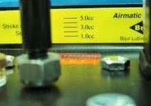
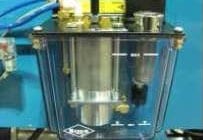
Bend Arm Lube Pump
Lubes swing arm and clamp gibs every N bends (per Lube Cycle Counter).
Lube Cycle Time sets pulse duration (factory ~200 ms).
Pump output set to 2 cc (factory). If ways drip, increase Lube Cycle Counter (do not reduce pump below 2 cc).
Low lube level triggers a software alarm.
Oil: Conoco Multi-Way Machine Lubricant.
Air Line Lubricator
Lubes all air devices; check every 3 months.
To fill: Lift/turn right reservoir to release and remove.
Oil: Conoco Velocite Oil #3.
Sight gauge on reservoir indicates level.
Hydraulics
Reservoir ~40 gallons. Oil: A/W 46 (Citgo).
Flow (front lock bolt): Factory set—do not adjust.
Pressure (rear/side locked bolt): Set to 1000 psi max (do not exceed).
Swing arm speed is controlled by software, not flow/pressure screws.
Hydraulic Filter: 10-micron element with clog sensor. Replace annually along with oil to protect the servo valve.
To replace: Pump OFF, close main valve, remove canister, replace element.
[Images: Hydraulic unit • Filter & sensor]
11. Safety Plate
Dual-sided yellow swing-arm safety plates stop the arm and turn off the pump if pressed.
Wired in series with the Emergency Stop—both must be released for the pump to start.
Test by pressing either plate; pump should stop and motion cease.
Adjust trigger via the two angled cogs and switch base plate if needed.
[Images: Safety plate trigger switch • Adjustment points]
12. Diagnostics
Quick Diagnostics (View Control Signals)
End-user view for key inputs (limits/pushbuttons).
Some inputs require E-Stop released to function.
Full Machine Diagnostics (Technician)
Displays all Inputs / Outputs / Control Signals / Master Flags.
Set Bit tool toggles outputs for testing (technician only—hazardous).
Program 0 & 1 Current Line shows controller execution lines.
Print button prints the current signal grid.
[Images: Diagnostics overview • Machine I/O screen]
13. Alarms
Low Air Pressure: Triggers below ~80 psi. Stop table devices may malfunction below this pressure.
Setpoint adjustable on the internal switch (trip near 80 psi, restore ~60–70 psi).Change Hydraulic Filter: Filter backpressure high or element damaged. Replace filter.
Lube Oil Low: Refill the lube reservoir to MAX with Conoco Multi-Way Machine Lubricant.
[Images: Air pressure switch • Hydraulic filter canister • Lube reservoir fill cap]
14. Troubleshooting
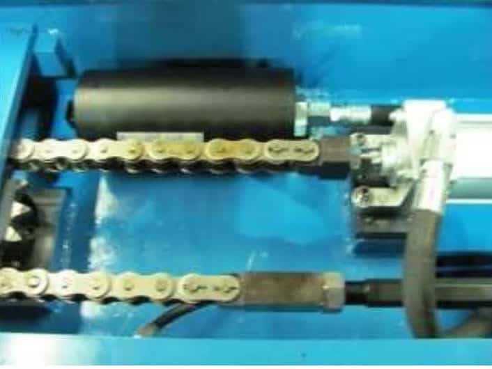
Pressure Drops Below 450 psi (Bend slows/jerks)
Likely accumulator discharged; recharge to 500 psi nitrogen. Accumulator must be removed for recharge; cannot ship charged by carrier.
Located in the chain/bend cylinder compartment on top of the bender.
Erratic Stop Table Motion (Single or Multi-Stop)
Loose Table Belt: Tension at mid-belt; ~0.5 in vertical travel; do not drag or flop.
Incorrect Gains/Speeds: Compare to OEM datasheet and restore.
Single-Stop specific
Marks/scratches on rail near locking pad → Stop Unlock Delay too short (default 500 ms).
Multi-Stop specific
Lock not engaging/disengaging → Stop Unlock Delay too short or air < 80 psi.
Erratic Bend Arm Motion
System pressure 900–1000 psi and accumulator 500 psi required.
Check arm encoder chain tension.
Check encoder readout stability at rest; verify angle change during moves. Replace encoder if noisy/unstable.
Verify arm chain is tight (no flex). Re-check Arm Home Offset after chain adjustments.
Compare Gains/Speeds to OEM datasheet; incorrect values can cause errors and damage the servo valve.
Clamp Problems
Clamps/Drawbar use dual-ended 24 VDC solenoids. For one motion to occur, the opposing solenoid must release to center.
If clamp won’t release (or vice versa):
Test Manual Mode clamp/unclamp. If OK, check clamp delays in parameters (not zero).
Observe relays & solenoid lights during clamp/unclamp. Replace failing components as needed.
Relay/Solenoid Logic Reference
System Clamp Forward (Clamp Fwd / Drawbar Down) Clamp Reverse (Clamp Rev / Drawbar Up) Benders ≤ 20025 CR2=ON (Sol A), CR3=ON (Sol B), CR4=OFF (Sol B), CR5=OFF (Sol A) CR2=OFF (Sol A), CR3=OFF (Sol B), CR4=ON (Sol B), CR5=ON (Sol A) Benders ≥ 20026 Safety Relay ON (K10.171 & K10.91), K10.021=ON (Sol B), K10.031=OFF (Sol B), K10.041=OFF (Sol A) Safety Relay OFF (K10.171 & K10.91), K10.021=OFF (Sol B), K10.031=ON (Sol B), K10.041=ON (Sol A) Location notes:
Solenoid A = front solenoids. Drawbar valve closest; middle valve = clamps; furthest = hydraulic servo valve (bend arm).
If relays follow the table but action fails, suspect the solenoid. Minland recommends replacing all four relays together if one fails.
15. Machine Fluids (Reference)
| System / Point | Specification |
|---|---|
| Hydraulic Fluid (≈ 40 gal) | A/W 46 (Citgo) |
| Hydraulic Filter | 10-micron element |
| Way Lube / Lube Pump Oil | Conoco Multi-Way Machine Lubricant |
| Pneumatic (Air) Lubricator Oil | Conoco Velocite Oil #3 |
| Grease Fittings | Citgo MP Lithoplex |
16. Support & Registration
- For software registration, provide Minland Machine the Software Machine ID from the Registration screen to receive a license code.
- For technical assistance (accumulator recharge, replacement filters, solenoids, relay sets, parameter baselines), contact Minland Machine with your Bender Serial Number and Bender Type.
Need CNC Expertise?
Minland Machine utilizes the best equipment, technology, and people to produce the highest quality CNC machining in the industry. Contact us for your next project.